
The direct-drive recumbent
The direct-drive recumbent bicycle is front-wheel-drive and has a crank axle aligned with the front wheel axis. There is no chain, and gear ratios are obtained by a transmission within the front hub itself. This results in a very simple bicycle design, with full-size wheels ideally positioned for an even weight distribution, giving excellent low-speed balancing, a smooth ride, and low rolling resistance. The front wheel is sufficiently well forward for full braking without going over the handlebars. Since the seating position is not too low, the rider’s eyes face horizontally forward without neck strain. The rider sits at a similar height to that of a car driver, giving good interaction in traffic. With the low crank position, the rider can readily place feet flat on the ground, making the bike user-friendly and well suited for in-town and recreational riding. Also, the cargo carrying capacity of the direct-drive recumbent is impressive due to the amount of space made available under the seat by the long wheelbase and absence of chain. Advantageously, the weight of the cargo is centrally located and low down, not disturbing the handling of the bike.

Best design practices
Driving the front wheel directly with the pedals causes the pedaling forces to be transmitted to the front fork. Since the front fork does the steering, there is pedal force feedback to the steering that the rider must resist through the handlebars. This force is not excessive when the bicycle’s frame and fork geometry is correctly designed. It is worth noting that pedal force feedback is common in every bike when the rider stands off the seat for extra force and resists the side-to-side frame motion with the hands through the handlebars. Garnet (2008) did a study of pedal force feedback in direct-drive recumbent bicycles. The study highlights the following best design practices:
Handlebars: The handlebars are best arranged in the above-seat steering position with the rider’s arms outstretched ahead. An inverted V or W shape gives the handlebars the greatest leverage for a given overall width, while providing the necessary knee clearance.
Optimum head angle: Inclining the head angle (angle of the steering axis) further back reduces the pedal force feedback, but there is no benefit in reducing it to less than 56 degrees to the horizontal. The higher the seating position, the higher the head angle can be. Generally the head angle should be in the range of 56 to 62 degrees to the horizontal.
Trail: The trail is the horizontal distance from the steering axis to front wheel ground contact point. The trail causes the front wheel to steer in the direction of the tilt of the frame, restoring balance automatically – even if the bike is ridden hands-free. It is essentially the caster effect. The amount of trail determines how quickly the steering reacts to a lean of the bicycle frame. In a regular bike, the trail is about 50 mm. A direct-drive recumbent should be designed with less trail due to a heavier weighted front wheel and a more inclined head angle. However, negative trail should not be used due to instability from ridges and other road surface imperfections. A formula for the trail is presented in the study. The formula indicates a trail of 25 mm for a head angle of 56 degrees and about 30 mm for a head angle of 62 degrees.
Centering spring: A centering spring is a spring that returns the steering to the center, i.e. to the straight ahead position. A centering spring is required for a direct-drive recumbent bike because the mass of the front assembly (everything that turns with the steering) is much larger than in a regular bike, due to the weight of the rider’s feet on the pedals. Without a centering spring, the steering would respond too strongly to a tilt of the frame or a slight turn of the steering, resulting in an over-correction to the steering. A centering spring controls these effects, restoring user-friendly handling and improving hands-free stability. The study presents an equation for determining the required spring constant for the centering spring. This spring can be a simple torsion bar placed in the head tube.
Wheelbase: Positioning the rear wheel immediately behind the seat back will result in a front wheel which is too lightly loaded, leading to traction problems particularly when going uphill. It is best to aim for a 50/50 weight distribution between the front and rear wheels with the rider on board. This result in a wheelbase ranging from 1300 to 1550 mm, depending on the size of rider.
Rigidity: In a regular bicycle, the torsional rigidity of the frame is important to ensure that a portion of the rider’s energy is not lost in frame flexure. For a direct-drive recumbent bike, it is rather the torsional rigidity of the front assembly that counts, particularly from the handlebars to the front wheel axle. This ensures that energy is not lost in structural flexure as the rider’s hands resist the pedal forces. The fork should be designed for good torsional rigidity.
History and development of the direct-drive recumbent
The bicycles of the 1860s, particularly those designed in France, were essentially semi-recumbents (Hadland and Lessing (2014)). Since they were front-wheel-drive and direct-drive, these bike were essentially the first direct-drive recumbent bicycles, albeit semi-recumbent and lacking a transmission hub or freewheel. The illustration below shows an example (from US patent 59,915 to Lallement).

1860s: Lallement bicycle
To achieve higher gearing, the size of the front wheel was gradually increased – leading to the well-known high wheeler bicycle, also known as the ordinary or penny-farthing. The large front wheel required the rider to have an upright posture, rather than semi-recumbent, so as to prevent interference between the rider’s legs and the circumference of the large wheel when steering. This upright riding position, combined with the height and forward position of the rider, resulted in a bicycle that was very unsafe, prone to throwing the rider from great height over the handlebars when a large bump was encountered, or under heavy braking. To address these safety concerns, the safety bicycle was introduced in the mid 1880s. This design, which has not changed significantly in layout to the present day, moved the rider to a lower, more rearward, position by employing chain-driven rear-wheel-drive. This reduced the pitch-over risk, but retained the same upright rider position of the “ordinary”. The alternative idea of addressing the safety issue by reducing the size of the front wheel and gearing-up the drive system was proposed in several designs, most notably the Crypto Bantam bicycle of the 1890s, shown below. As with the safety bicycle, this design placed the rider lower and slightly further back than the “ordinary” design, with ensuing safety benefits. However, the safety bicycle was already well established and the Crypto Bantam design did not catch on in significant numbers.

1893 Crypto Bantam. Front-wheel-drive with step-up planetary transmission
Shortly after this, in the early 1900s, bicycles with a true recumbent position – rather than merely semi-recumbent – were introduced (see below). However, these were chain-driven and rear-wheel-drive, a testament to the popularity of the “safety” bicycle.

1902 Jarvis recumbent: Early bike with full recumbent position
Surprisingly, the idea of combining a direct-drive front hub with a recumbent riding position was not proposed until about eighty-five years later. In 1987, Dirck Hartmann of California patented a direct-drive hub and front-wheel-drive recumbent, shown below from US patent 4694708. Hartmann’s also patented many other direct-drive hub designs.

1987: Direct-drive recumbent proposed by Hartmann
In the late nineteen nineties, Thomas Kretschmer of Berlin developed a direct-drive recumbent bicycle having a very shallow head angle (45 degrees). This bike (shown below, from German patent DE19736266 A1) included a centering spring for the steering to improve the handling. Kretschmer also proposed a multi-speed hub design (German Patent DE19824745 A1). Details of Thomas Kretshmer’s direct-drive hub and related bikes were also published in the journal Human Power (Kreschmer (2000)).

1999: Thomas Kretschmer’s direct-drive recumbent - low head angle and centering spring
In the early 2000s, John Stegmann of South Africa proposed a direct-drive recumbent bicycle design that takes full advantage of the cargo-carrying capacity afforded by the long wheelbase and absence of chain (Stegmann (2002)). Stegmann also emphasized the need for a viable hub for direct-drive. Stegmann’s design proposal motivated Jeremy Garnet to build a direct-drive recumbent bike to test the viability of the direct-drive recumbent (Garnet (2003)). The bike, illustrated below, used an adaptation of a Schlumf Speed-Drive™ bottom bracket gear to provide a basic single-speed direct drive hub.

2003: Jeremy Garnet’s direct-drive recumbent – first frame
A year later the original frame was replaced with a better quality frame and components, see below.

2004: Jeremy Garnet’s direct-drive recumbent – second frame
In 2008, a study (Garnet (2008)) was published to determine the required frame and fork geometry to minimize pedal force feedback and provide user-friendly handling. As part of this research, a variable-geometry frame was built, see below. A summary of the results of the study is given above in the “Best design practices” section.

In 2018, to test the Velotegra hub first prototype, Jeremy Garnet constructed a fourth direct-drive recumbent – shown below. The frame is made of epoxy-bonded and riveted 6061-T6 aluminum. The bike includes an “in-line” headset configuration, where the headset is positioned in-line along the down tube. A centering spring is concealed within the tube. The head angle is 56 degrees to the horizontal, and the wheelbase is 1500 mm.

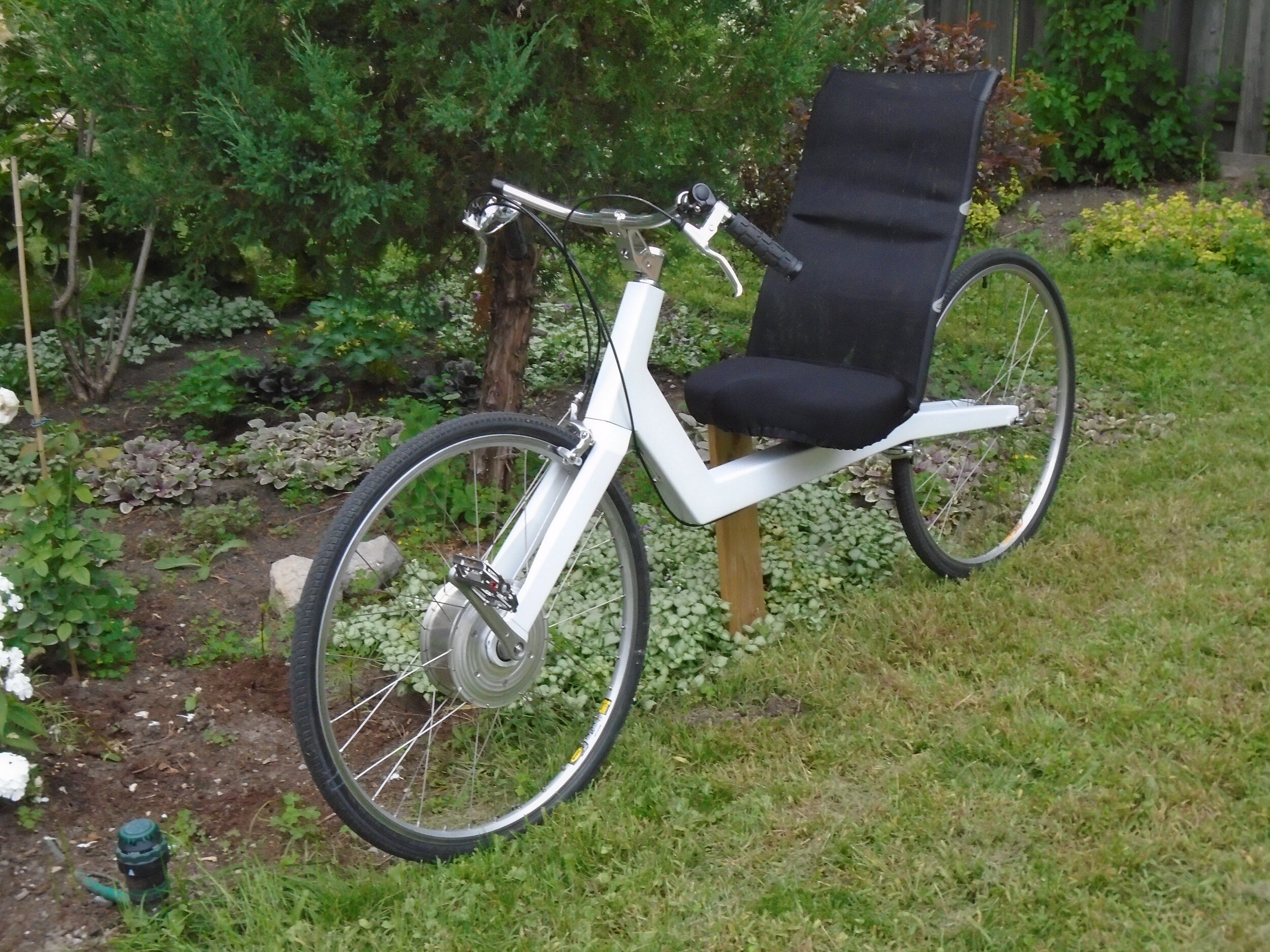
In 2020, Jeremy Garnet made a fifth bike with a more upright geometry, a more traditional headset arrangement, and wider handlebars. The bike, shown below, is lighter than the 2018 version and has a semi-monocoque frame made of 6061-T6 aluminum sheeting and angle pieces, epoxy bonded and riveted into a single piece. A centering spring is fitted and is formed of a torsion bar mounted in the steerer tube. The head angle is 62 degrees to the horizontal, and the wheelbase is 1450 mm.

References
Hadland and Lessing. (2014). Bicycle Design: an Illustrated History. Cambridge, Massachusetts. The MIT Press. p. 473.
Stegmann, John. (2002). “Chain of Thought”. Velo Vision, no. 8, pp. 22-25.
Kretschmer, Thomas (2000). “Direct-drive (chainless) recumbent bicycles”, Human Power, no 49:11-14.
Garnet, Jeremy. (2003). “Delving into Direct-Drive”. Velo Vision, no. 12, pp. 18-20.
Garnet, Jeremy (2008). “Ergonomics of Direct-Drive Recumbent Bicycles”, Human Power eJournal, Article 17, Issue 5.